 English
 Español
 Pусский
Precision control of the reciprocating stroke of a honing machine has always been a bottleneck restricting the high-speed development of honing machines. This article introduces a method that uses pulses emitted by a rotary encoder as CPU counting pulses to achieve precise control of the reciprocating stroke of the honing machine, thereby achieving a qualitative leap in the improvement of honing machine tool quality.
Traditional honing machine stroke control relies on a mechanical sprocket to convert linear motion into the collision of rotating blocks or sliders to change the reciprocating direction of the honing machine. The reciprocating stroke is achieved by adjusting the position of the slider and blocks, which has many inconveniences:
1. Due to manual operation, it is difficult to adjust the reciprocating stroke to the ideal position, and the adjustment is also inconvenient. (2) In addition, the slider collision is prone to wear and loosening, which can easily cause excessive deviation in the repeatability positioning accuracy when reciprocating in reverse. (3) The position of the collision block needs to be corrected frequently. (4) It is impossible to set when the reciprocating stroke is required to be small. (5) Since contact collision is prone to damage to the device, the maintenance cost is too high. Therefore, we use a rotary encoder as the control element in the CNC honing machine, which successfully overcomes the above-mentioned shortcomings.
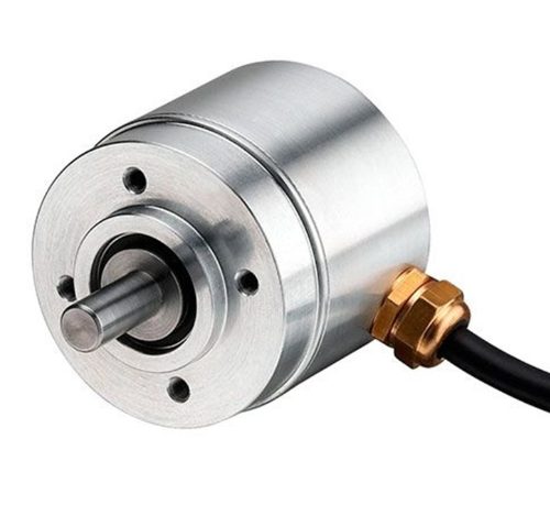
2. Encoder Selection
As we know, rotary encoders emit pulses in two phases: A-phase and B-phase. With these two phases, the PLC's CPU high-speed counting input can determine whether the rotary encoder is rotating in the forward or reverse direction based on their arrival order. If forward rotation is set to increment the count, then reverse rotation decrements it. Since this machine tool uses an Omron CJ1M programmable controller with a 100kHz high-frequency counting unit, its received pulse frequency must be limited. This limitation is used as a basis for encoder selection. The reciprocating speed of a typical honing machine is 3–30 m/min, meaning the maximum reciprocating speed is 500 mm/s. Assuming the encoder is directly driven by a pulley with a pulley diameter of 60 mm and a pulley circumference L = πD = 3.14 × 60 = 188.4 mm, the maximum encoder speed is 500 mm / 188.4 mm/s = 2.65 r/s. If the encoder outputs 10,000 pulses per revolution, the maximum encoder frequency is 2.65 ≤ 10,000 pulses / R = 26.5 kHz, which is much less than 100 kHz. Therefore, this machine tool uses an OMRON encoder. The E6B2-CWZ6C-2000P/R outputs 2000 A and B pulses per revolution. The CJ1M CPU takes the rising and falling edge transition signals of the pulses from the high-speed input terminal as counting signals. This is equivalent to quadrupling the frequency of the pulse signal emitted by the rotary encoder. That is, for every revolution of the rotary encoder, the CPU's high-speed counting unit counts at 2000P/R × 4 = 8000P/R. Even so, it will not exceed the CPU's maximum counting frequency. Therefore, no additional high-speed counting unit hardware is needed.
3. Setting up the high-speed counting unit
The high-speed counting input of the CJ1M programmable controller has linear and cyclic counting modes. The counting input of this machine tool is set according to the differential phase linear counting mode.
4. Principle
The coordinate values of the reciprocating points of the honing mill and the water ring position are stored in decimal (hexadecimal needs to be converted) in different DM addresses in the CJ1M data register area. These values are used as target values. The accumulated count or accumulated count value transmitted from the high-speed counting input terminal is the current value. The current value is compared with several target values. The comparison result sends an interrupt to control whether the spindle reciprocates downward or upward.
As mentioned earlier, the encoder pulley diameter D = 60mm, the encoder pulley circumference L = 188.4mm, and the number of pulses emitted per encoder revolution: 2000 × 4 times the frequency = 8000. Each encoder pulse represents the reciprocating distance, i.e., the pulse equivalent, pulse equivalent = 188.4/8000 = 0.02356mm/P. Based on this pulse equivalent, the distances (pulse counts) from the zero point of the water ring to the upper reversing point, lower reversing point, and upper limit point can be calculated. These distances can be used as the coordinates of their target values, and the difference between the coordinates of the upper and lower reversing points is the reciprocating stroke distance. Once the spindle reciprocating stroke is determined, changing the coordinate values of the upper and lower reversing points can change the spindle reciprocating stroke range. These values can be set directly through the touch screen. The data is transmitted to the DM area register of the CJ1M according to the communication protocol between the touch screen and the CJ1M (the communication between the touch screen and the CJ1M will not be described further).
 Lily
Lily